In this guide we describe how to configure your FortiGate wireless LAN controller wireless LAN controller devices to work with OpenRoaming and SIM card authentication
Prerequisites
- Access to the FortiGate Dashboard as a user with administrative privileges.
- Information about the assigned RADIUS servers (Server IP address, port numbers, shared secrets):
- Email or document that contains this information
OR - Access to the IronWiFi Management Console - Sign in or Open Account
- Email or document that contains this information
Log in to the FortiGate Dashboard
To start the configuration process, log in to the FortiGate Dashboard as admin. For existing
environments with additional users, log in as a user with administrative privileges.
.png?width=310&height=181&name=image-000%20(1).png)
The FortiGate Dashboard appears. Your access points are displayed in the Security section.
.png?width=652&height=320&name=image-001%20(1).png)
Note: There are a number of options you can set. Only the options that require your input are
shown. Default values are used for options that don’t need adjustment.
Configure the wireless LAN
To configure the wireless LAN, you create a new SSID for IronWiFi, a RADIUS server, and
an IPv4 policy.
Create an SSID
1. Select Wifi & Switch Controller and then SSID in the menu bar on the left of the
Dashboard.
.png?width=233&height=431&name=image-002%20(1).png)
2. Click +Create New at the top left and select SSID.
.png?width=147&height=94&name=image-003%20(1).png)
The New SSID page appears.
.png?width=688&height=825&name=image-004%20(1).png)
.png?width=688&height=781&name=image-005%20(1).png)
Define the SSID interface
When you create an SSID, you’re creating a software interface and allowing traffic on that
interface. Before creating the SSID, you define the interface for it.
1. Enter an Name, such as “IronWiFi”.
Alias is optional.
2. For Type, select WiFi SSID.
3. For Traffic Mode, select the traffic mode that’s appropriate for your network.
.png?width=432&height=188&name=image-006%20(1).png)
Set the IP address
Enter the IP address and network mask for the SSID interface.
.png?width=421&height=67&name=image-007%20(1).png)
Define network access
Select HTTPS, HTTP, and RADIUS Accounting. You can select additional options, such as
SSH, as appropriate for your network.
.png?width=533&height=109&name=image-008%20(1).png)
Supply DHCP server information
Enter DHCP information that’s appropriate for your network.
.png?width=688&height=323&name=image-009%20(1).png)
Describe WiFi settings and add a RADIUS authentication server
The RADIUS server information you add here is for the RADIUS authentication server. You’ll
add RADIUS accounting server information later when you configure Hotspot 2.0.
1. Enter the name of your SSID, such as “IronWiFi”.
2. Change Security Mode to WPA2 Enterprise. (WPA Personal is the default.)
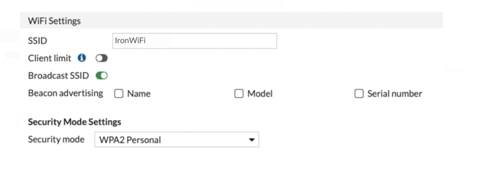
3. For Client MAC Address Filtering, enable RADIUS Server.
4. Click ⌄ below to enable RADIUS Server.
.png?width=458&height=72&name=image-011%20(1).png)
5. Click on drop down button and select + to add a RADIUS server.
.png?width=377&height=52&name=image-012%20(1).png)
The New RADIUS Server page appears.
.png?width=499&height=416&name=35.189.111.2%20(15).png)
6. Enter a Name, such as “radius1”.
7. For the Primary Server, enter the IP address of the RADIUS server.
8. For Secret, enter assigned RADIUS shared secret.
Note: Don’t test connectivity at this point. To successfully test connectivity, you need a
complete IPv4 policy to allow traffic on the interface.
9. If there is a secondary RADIUS server, enter its RADIUS IP address and also the assigned RADIUS shared secret for Secret in the Secondary Server section.
A secondary RADIUS isn’t required but you can create one for high availability.
10. Click OK at the bottom of the New RADIUS Server page.
You return to the New SSID page.
11. Select the RADIUS server you added.
12. Click OK at the bottom of the New SSID page to save your SSID configuration.
Configure an IPv4 Policy
Add an IPv4 allow policy on the FortiGate wireless LAN controller to allow traffic from the
SSID to reach the Internet.
1. Select Policy & Objects and then Firewall Policy in the menu bar on the left of the
dashboard..png?width=302&height=355&name=image-014%20(1).png)
2. Click +Create New at the top left.
.png?width=232&height=72&name=image-015%20(1).png)
The New Policy page appears.
.png?width=688&height=673&name=image-016%20(1).png)
3. Enter a Name for this policy, such as “IronWiFi_policy”.
4. For Incoming Interface, enter the name of the SSID interface you created,
“IronWiFi_int”.
5. For Outgoing Interface, enter the name of the Interface in your network that routes
traffic to the Internet.
6. For Source, enter the IP address range from which you want to allow incoming traffic.
Or select all to allow incoming traffic from any IP address.
7. For Destination, select all to send outgoing traffic to any IP address unless you have
blacklisted subnets.
8. For Schedule, select always.
9. For Service, select ALL.
10. For Action, select ACCEPT.
11. Click OK at the bottom of the page to save your configuration.
Configure Hotspot 2.0
Hotspot 2.0 allows mobile devices to join a WiFi network automatically, including during
roaming, when the devices enter the Hotspot 2.0 area.
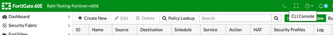
You configure Hotspot 2.0 using a command line interface (CLI). Access the CLI by launching
a terminal session or selecting > _ CLI Console at the top right of the Dashboard.
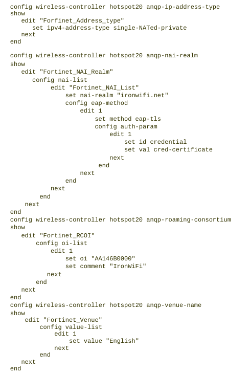
Configure ANQP Parameters
Access Network Query Protocol (ANQP) provides a range of information, such as IP address
type and availability, and roaming partners accessible through a hotspot.
1. Set the ANQP IP address type as appropriate for your network. This example shows a single NATed network.
config wireless-controller hotspot20 anqp-ip-address-type
edit "Fortinet_Address_type"
set ipv4-address-type single-NATed-private
next
end
2. Configure the ANQP NAI realm and EAP authentication.
config wireless-controller hotspot20 anqp-nai-realm
edit "Fortinet_NAI_Realm"
config nai-list
edit "Fortinet_NAI_List"
set nai-realm "ironwifi.net"
config eap-method
edit 1
set method eap-tls
config auth-param
edit 1
set id credential
set val cred-certificate
next
end
next
end
next
end
next
end
3. Configure the ANQP roaming consortium.
config wireless-controller hotspot20 anqp-roaming-consortium
edit "Fortinet_RCOI"
config oi-list
edit 1
set oi "AA146B0000"
set comment "IronWiFi"
next
end
next
end
4. Configure the ANQP venue name.
config wireless-controller hotspot20 anqp-venue-name
edit "Fortinet_Venue"
config value-list
edit 1
set value "English"
next
end
next
end
5. Use the show command to verify the configuration. The output should look similar to this example.
Configure a RADIUS accounting server
1. Configure a RADIUS accounting server.
config user radius
edit 1
set server <RADIUS IP address>
set secret <RADIUS shared secret>
next
end
2. Use the show command to verify the configuration. The output should look similar to this example. Notice that the secret is encrypted.
config user radius
show
config user radius
edit "radius1"
set server "_________"
set secret ENC
ZRie...........Ol3URpA==
set password-renewal disable
next
end
Configure the Hotspot 2.0 profile
You attach the ANQP parameters and SSID to the Hotspot 2.0 profile.
1. Attach the ANQP parameters to the Hotspot 2.0 profile.
config wireless-controller hotspot20 hs-profile
edit "Hotspot"
set domain-name "ironwifi.net"
set roaming-consortium "Fortinet_RCOI"
set nai-realm "Fortinet_NAI_Realm"
set ip-addr-type "Fortinet_Address_type"
next
end
2. Attach the Hotspot 2.0 profile to the SSID.
config wireless-controller vap
edit "IronWiFi"
set hotspot20-profile "Hotspot"
next
end
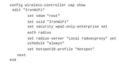
3. Use the show command to verify the configuration. The output should look similar to this example.
Troubleshoot the configuration
RCOI and EAP settings
If the Roaming Consortium Unique Identifier (RCOI) and EAP method aren’t set correctly,
mobile devices can’t automatically connect (which is intended). If radsecproxy logs are
showing an attempt to connect but failing, it means radsecproxy IP addresses are probably
correct in the RADIUS authentication and accounting settings, but the EAP settings could be
wrong.
Review Configure Hotspot 2.0 and make sure your configuration is correct.
RADIUS service
If the IP addresses or secrets used for the primary and secondary servers are wrong, the
RADIUS server can’t be contacted. In this situation, radsecproxy logs can’t be generated,
because traffic isn’t passing to the wireless LAN controller from radsecproxy.
If no new logs are coming in, it means the SSID isn’t passing traffic to radsecproxy. If this is
the case, you should check the RADIUS configuration.
Review Describe WiFi settings and add a RADIUS authentication server and Configure a
RADIUS accounting server to make sure your RADIUS configuration is correct.
IPv4 Policy for SSID interface
If the policy for the new SSID interface is missing or isn’t allowing access to the Internet,
clients authenticate but indicate “WiFi connected but no Internet”.
Review Configure an IPv4 Policy and make sure your configuration is correct.
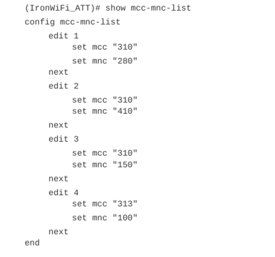
AT&T MNC / MCC Configuration
1. You configure cellular based Hotspot 2.0 configuration using a command line interface
(CLI). Access the CLI by launching a terminal session or selecting > _ CLI Console at
the top right of the Dashboard.
Note: You can also ssh into the Fortigate controller to access the CLI.
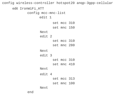
2. Use the show command to verify the configuration. The output should look similar to
this example.