In this guide we describe how to configure your Cisco Catalyst 9800 devices to work with OpenRoaming and SIM card authentication
Prerequisites
- Access to the Cisco WLC Dashboard as a user with administrative privileges.
- Information about the assigned RADIUS servers (Server IP address, port numbers, shared secrets):
- Email or document that contains this information
OR - Access to the IronWiFi Management Console - Sign in or Open Account
- Email or document that contains this information
Log in to the Cisco Catalyst 9800 Series Wireless Controller Dashboard
To start the configuration process, log in to the Cisco Catalyst 9800-CL Wireless Controller Dashboard as admin. For existing environments with additional users, log in as a user with administrative privileges.
The Cisco Catalyst 9800-CL Wireless Controller Dashboard appears. Your access points are displayed.

Note: There are a number of options you can set. Only the options that require your input are shown. Default values are used for options that don’t need adjustment.
Set up a secure RADIUS connection
It’s important to set up a secure RADIUS connection between the wireless LAN controller and IronWiFi. We recommend that you create a primary and a secondary RADIUS server for high availability. Then create a server group and add those servers to the group.
Add RADIUS authentication and accounting servers
- Select Configuration > Security > AAA from the menu on the left side of the Dashboard.
The AAA page appears. - Make sure that RADIUS and Servers are selected.
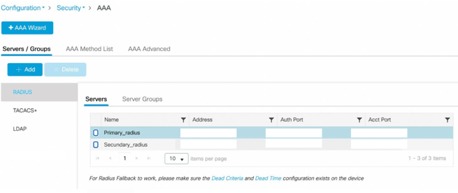
- Click + Add under Servers/Groups.
The Create AAA Radius Server dialog box appears..png?width=655&height=366&name=35.189.111.2%20(16).png)
- Enter a Name, such as “Primary_radius”.
- For the Server Address enter the IP address of the Primary Radius server (from the Console)
- For Key, enter the value that will be communicated by IronWiFi, then enter the same value for Confirm Key.
- Verify that Auth Port is auth port from the Console (RADIUS authentication) and Acct Port is acct port from the Console (RADIUS accounting).
- For Server Timeout, enter “30” seconds. This is the maximum timeout as recommended in RFC 5080.
- Click Apply to Device on the bottom right.
You return to the AAA page where the server you added is listed.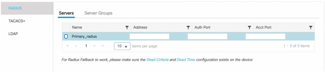
- To review or edit server values, select the server in the list.
.png?width=655&height=325&name=35.189.111.2%20(17).png)
- Repeat steps 3-10 to add the Secondary RADIUS server (from the Console)
Add a RADIUS server group
Using a server group, you can separate IronWiFi authentication requests from the rest of your network. If you don’t create a server group, the controller will send authentication requests to the default server group, which might contain servers that aren’t associated with IronWiFi.
- Navigate to Configuration > Security > AAA.
- On the AAA page, under Servers/Groups, select the Server Groups tab.
- Make sure that RADIUS and Server Groups are selected.
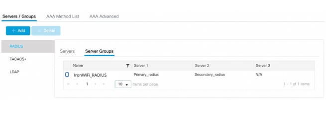
- Click + Add under Servers/Groups.The Create AAA Radius ServerGroup dialog box appears.
- Enter a Name, such as “IronWiFi_RADIUS”.
- Select all of your RADIUS servers under Available Servers.
- Click > to move the servers to Assigned Servers.
You see a message indicating that the configuration was saved. You return to the AAA page where the server group you added is listed.
Create AAA Method List
- Navigate to Configuration > Security > AAA > AAA Method List
- Select the Authentication tab and click + Add
The Quick Setup : AAA Authentication box appears.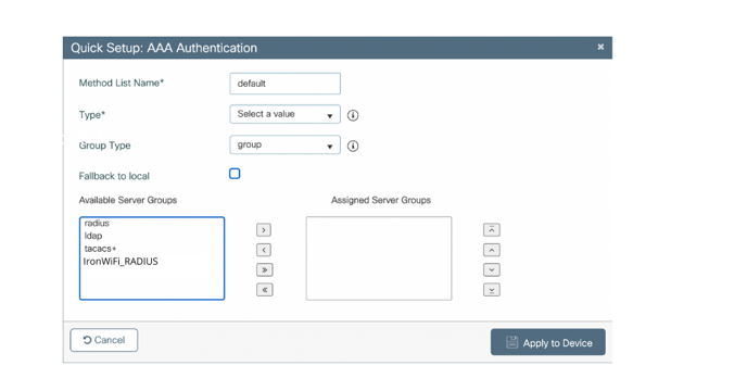
- Enter a Method List Name, such as “guest_auth”.
- For the category Type select dot1x from the drop-down menu.
- For the category Group Type select group from the drop-down menu.
- Select all of the RADIUS servers group previously created under Available Server Groups.
- Click > to move the servers to Assigned Servers Groups.
- Click Apply to Device on the bottom right.
- Select the Accouting tab on the left and click + Add
The Quick Setup : AAA Accouting box appears. - Enter a Method List Name, such as “guest_acct”.
- For the category Type select identity from the drop-down menu.
- Select all of the RADIUS servers group previously created under Available Server Groups.
- Click > to move the servers to Assigned Servers Groups.
- Click Apply to Device on the bottom right.
Configure the WLAN AA Policy
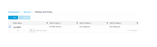
- Navigate to Configuration > Security > Wireless AAA Policy
- Click + Add
The Add Wireless AAA Policy dialog appears.
3. Enter a Policy Name such as "IronWiFi"
4. On NAS-ID Option 1 select AP MAC Address
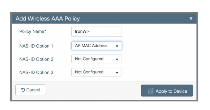
5. Click Apply to Device on the bottom right.
Configure Hotspot 2.0
Hotspot 2.0 allows mobile devices to join a WiFi network automatically, including during roaming, when the devices enter the Hotspot 2.0 area.
Configure ANQP Server Parameters
Access Network Query Protocol (ANQP) provides a range of information, such as IP address type and availability, and roaming partners accessible through a hotspot.
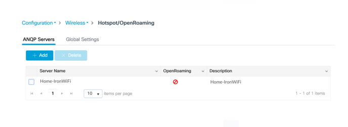
- Select Configuration > Wireless > Hotspot/OpenRoaming from the menu on the left side of the Dashboard.
The Hotspot/OpenRoaming page appears.

2. Click + Add under ANQP Servers.
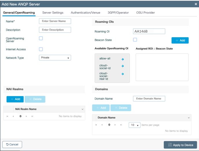
The Add New ANQP Server dialog box appears. The General/OpenRoaming tab is selected.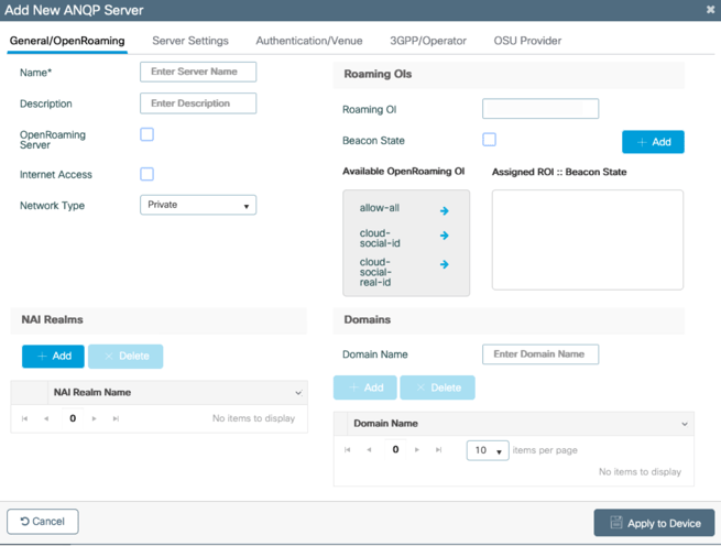
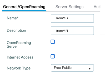
General/OpenRoaming settings
- In the Add New ANQP Server dialog box, enter a Name for the server, such as “IronWiFi”.
- Check the box next to Internet Access.
- For Network Type, select Free Public.
4. In the NAI Realms section on the bottom left, click + Add.
The Add NAI Realm page appears.
5. For NAI Realm Name, enter the value associated with your home network domain, as provided in the IronWiFi dashboard
6. For EAP Method, select eap-ttls.
An EAP-TTLS dialog box appears.
7. Select inner-auth-non-eap, and check to box next to mschap2. T
his is the EAP authentication method.
8. Click Save at the bottom of the EAP-TLS dialog box.
9. Click Apply to Device at the bottom of the Add NAI Realm dialog box.
You see your real, such as "ironwifi.net" listed as an NAI realm.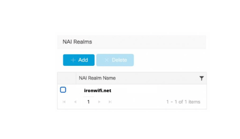
10. To enable also OpenRoaming, in the Roaming OIs section on the top right, enter “AA146B0000” for Roaming OI.
11. Click + Add.
12. Repeat the same steps to add also the Roaming OIs "AA146B".
You see the RCOI under Assigned ROI :: Beacon State.
13. Check the box next to Beacon State. This includes the RCOI in access point broadcasts.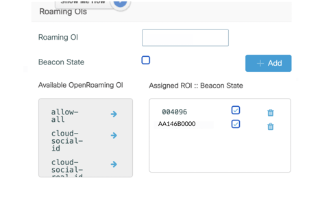
14. In the Domains section, enter your home network domain, as provided in the IronWiFi dashboard, such as “ironwifi.net” for Domain Name
15. Click + Add.
You see the domain name in the Domain Name list.

Server Settings
1. Still on the Add New ANQP Server dialog box, select Server Settings at the top.
The Server Settings page appears.
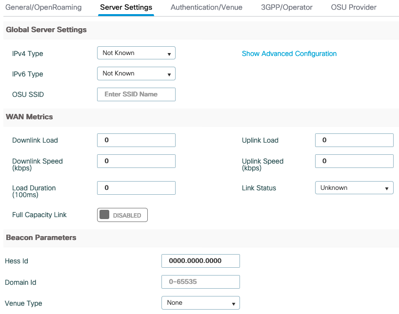
2. In the WAN Metrics section, set the parameters as appropriate for your network. Don’t leave these values blank.
3. Set Link Status to Up.
4. Don’t enable Full Capacity Link unless you want to block devices from connecting. This setting tells devices that there’s no bandwidth available so devices will refuse to connect.
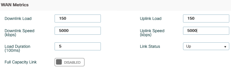
5. Click Apply to Device at the bottom right.
You see a message indicating that the configuration was saved. You return to the Hotspot/OpenRoaming page where the ANQP server you added is listed.
Configure the Wireless LAN Profile
To configure the wireless LAN, you create an SSID to identify the wireless LAN. Then you associate the security profile and RADIUS servers with the wireless LAN.
Create the SSID
1. Select Configuration > Tags & Profiles > WLANs from the menu on the left side of the Dashboard.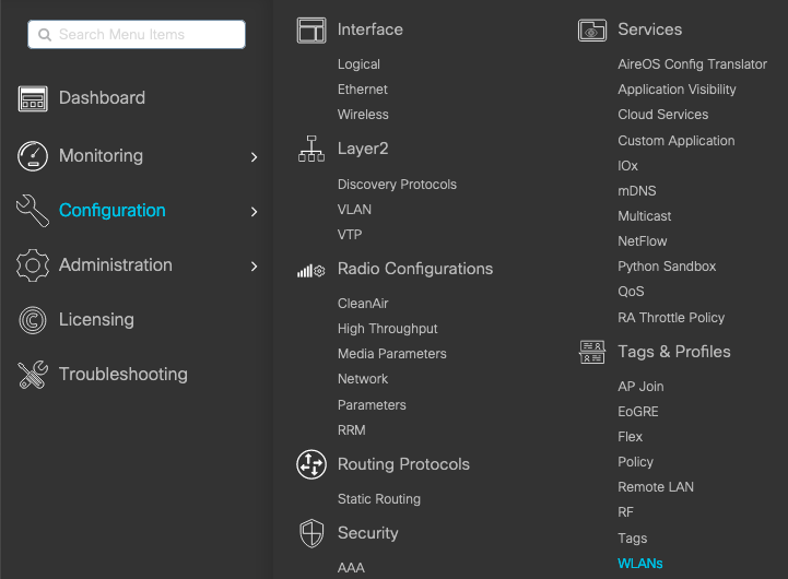
The WLANs page appears.

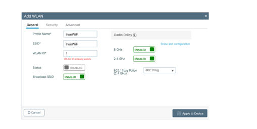
2. Click + Add.
The Add WLAN dialog box appears. The General tab is selected.

3. Enter a Profile Name, such as, “IronWiFi”.
4. For SSID, enter your SSID name, such as “IronWiFi”.
5. Change Status to Enabled.
6. Click Apply to Device on the bottom right.
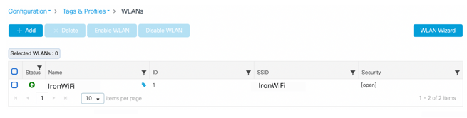
You see a message indicating that the configuration was saved. You return to the WLANs page where the wireless LAN you added is listed.
Associate the security profile and RADIUS servers with the wireless LAN
1. Navigate to Configuration > Tags & Profiles > WLANs.
2. Select the wireless LAN you added. The Edit WLAN page appears.
3. Select Security at the top. The Layer2 tab is selected.
4. For Layer 2 Security Mode, select WPA + WPA2 (default).
Note: do not use a security level lower than “WPA2 + WPA3”, otherwise you might get a “Security Weak” error on iOS.
5. Verify that the boxes next to these security options are checked:
WPA2 Policy
WPA2 Encryption AES(CCMP128)
Auth Key Mgmt 802.1x

6. Select AAA at the top.
7. Select the Authentication list created earlier from the drop down menu, “guest_auth”.
Configure Policy Profile
A Policy Profile enables you to assign parameters like VLAN, Access Controls List [ACLs], Quality of Service [QoS].
1. Navigate to Configuration > Tags & Profiles > Policy > ADD+2. The Add Policy Profile page appears.
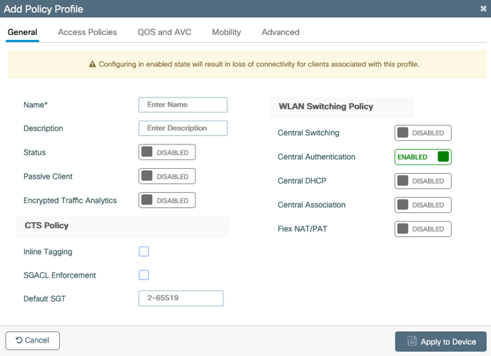

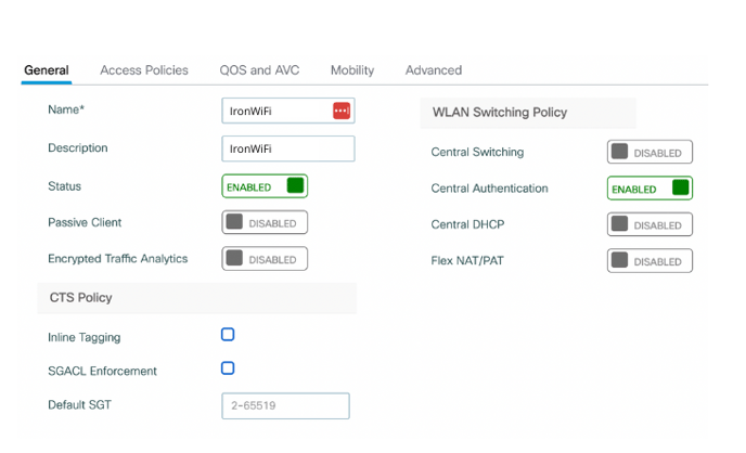
3. Enter a Policy Name, such as, “IronWiFi”
4. Enter a Policy Description, such as, “IronWiFi”
5. Enable the Status of this profile by clicking on the category.
The Access Policies page appears as below:
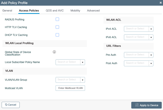

7. Enter the VLAN ID allocated for IronWiFi WLAN, in case of default VLAN type the number 1. DO NOT leave this field blank or select default from the drop down menu.
8. Still on the Add Policy Profile dialog box, select Advanced option at the top.
The Advanced Option page appears:
9. Under the WLAN Timeout section, uncheck the Client Exclusion Timeout option10. Under Hotspot Server option (Top right) select the Hotspot Server name configured earlier, “IronWiFi”.
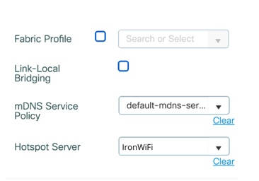
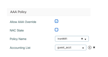
11. Under AAA Policy (Bottom Left) check the box next to Allow AAA Override and
as Policy Name select the Wireless AAA Policy created before (e.g. "IronWiFi")
as a Accounting List select the Accounting List created before (e.g. IronWiFi")
12. Click Apply to Device at the bottom right.
Configure Policy Tag
A Policy tag is configured to connect the WLAN Profile to the Policy Profile.
1. Navigate to Configuration > Tags & Profiles > Tags > Policy > ADD2. The Add Policy Tag dialogue box appears.
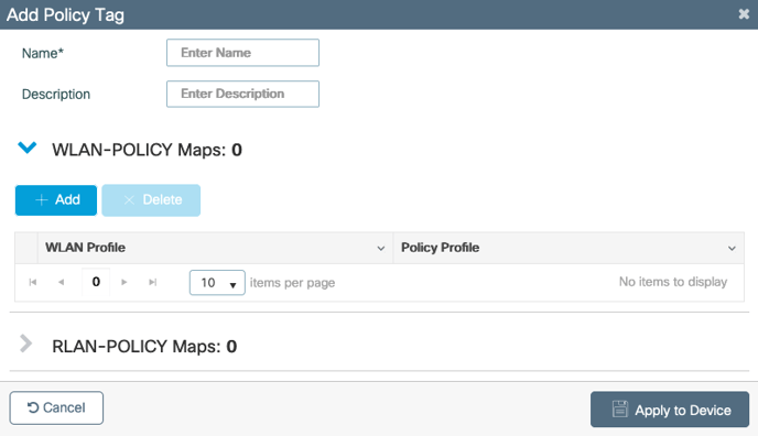
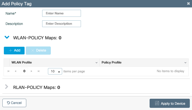
3. Enter a Profile Name, such as, “IronWiFi”.
4. For Description, enter “IronWiFi”.
5. Click on ADD under WLAN-POLICY Maps

7. Select the Policy Profile configured earlier from the drop down menu option ("IronWiFi").

8. Click on the check mark below
Assign Policy Tag
To deploy configured policies to the Access Points each Policy Tag should be attached to the required Access Point.
1. Navigate to Configuration > Wireless Setup > Advanced > Start Now > Apply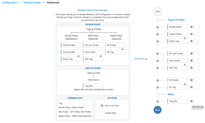
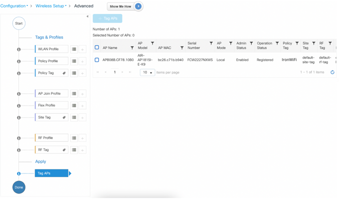
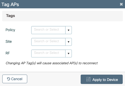
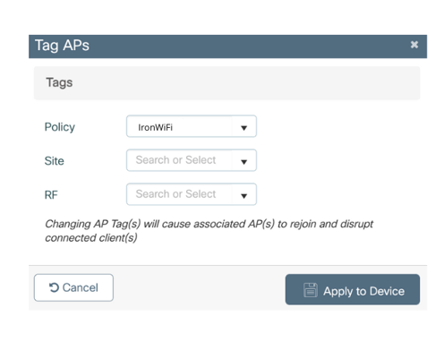
4. The Tag APs dialogue box appears
AT&T MNC / MCC Configuration
1. Select Configuration > Wireless > Hotspot/Openroaming from the menu on the left
side of the Dashboard.
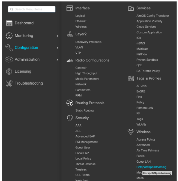
The Hotspot/OpenRoaming page appears.
2. Click + Add under ANQP Servers.
The Add New ANQP Server dialog box appears. The General/OpenRoaming tab is
selected.
3. To add MCC/MNC codes for cellular based authentication select the 3GPP menu from
the top
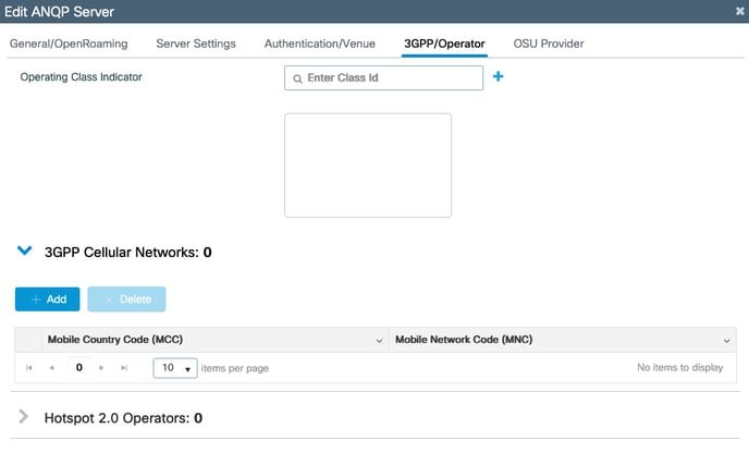
4. Click on the +Add button and insert the MCC/MNC code under the 3GPP Network
Details. Each set of code to be inserted one at a time.
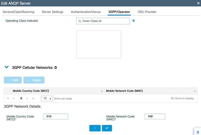
5. Click on the ‘Check mark’ to register the entered MCC/MNC code pair. Repeat the
process for Step 2 & 3 to add the following codes.
● MCC (310) ; MNC (410)
● MCC (310) ; MNC (280)
● MCC (310) ; MNC (150)
● MCC (313) ; MNC (100)
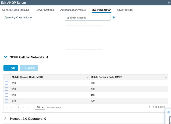
6. Click Apply to Device at the bottom right.
You see a message indicating that the configuration was saved. You return to the
Hotspot/OpenRoaming page where the ANQP server you added is listed.